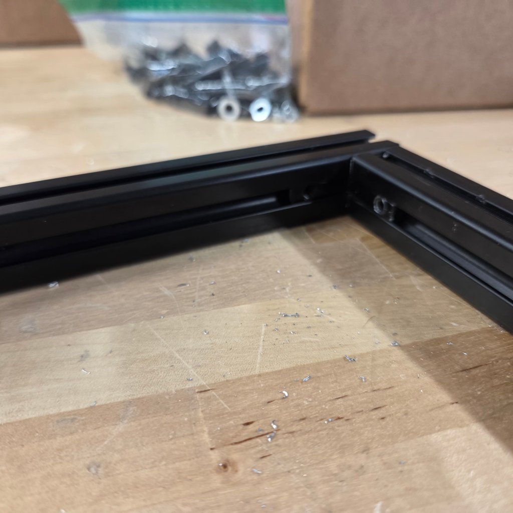
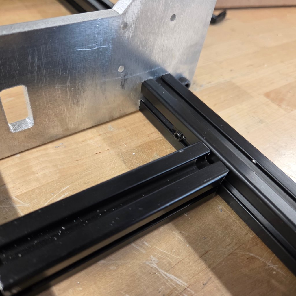
with your cut pieces, place two long ones together, one short one together and place an L bracket and screw them together (The L brackets may be challenging to put in, you can file down the cut pieces.
The orientation should look something like this, and with your frame, place it to whatever side it fits and screw the bolts on the other side to fit into the steel beam pieces.
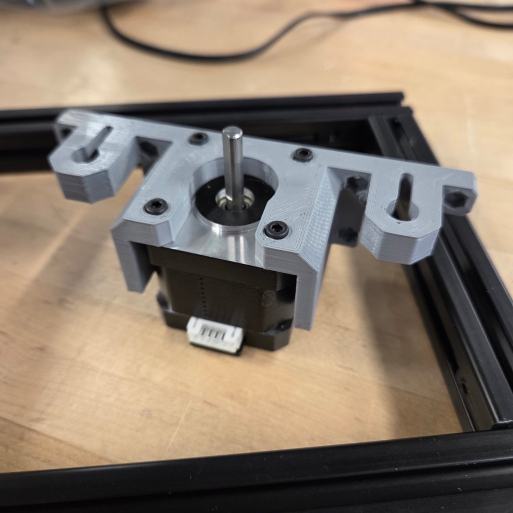
More L bracketing.Place a motor into this piece, make sure the white outlet is stick this direction (it makes things a lot easier)Another motor should go under this piece, and place the heat-set inserts in the holes.
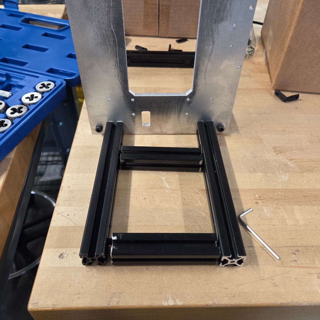
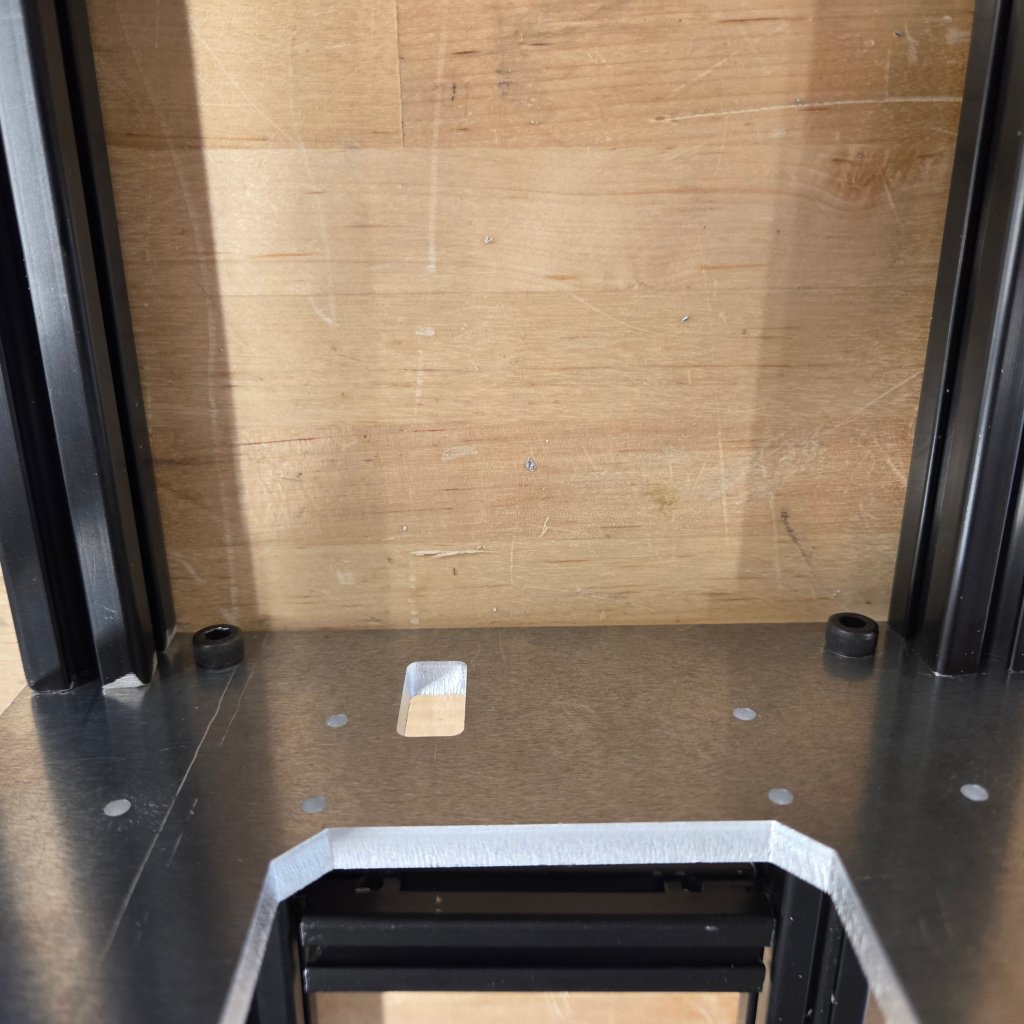
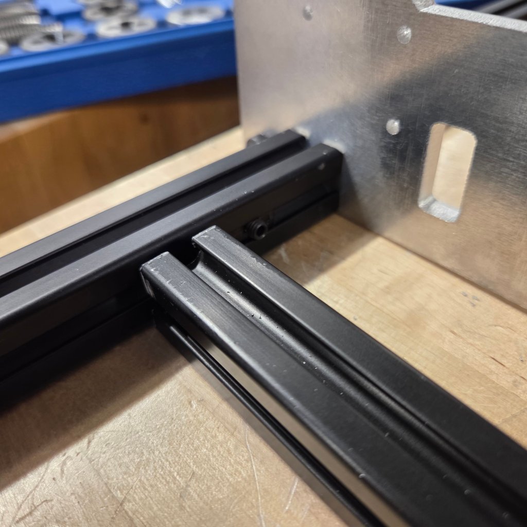
Place this piece onto the two beams, and then place L brackets on the small sides in the orientation shown
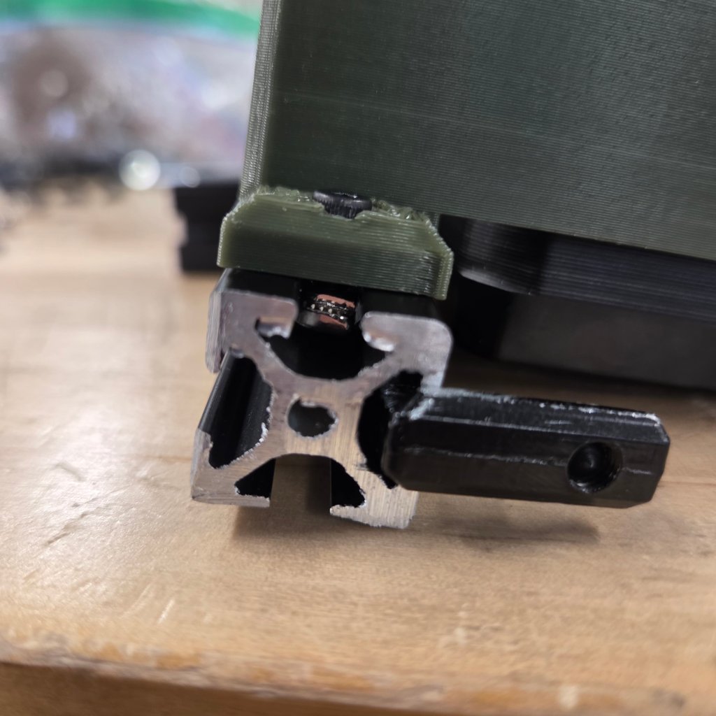
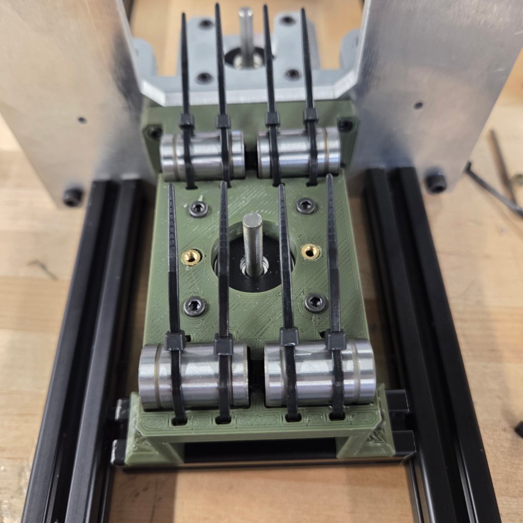
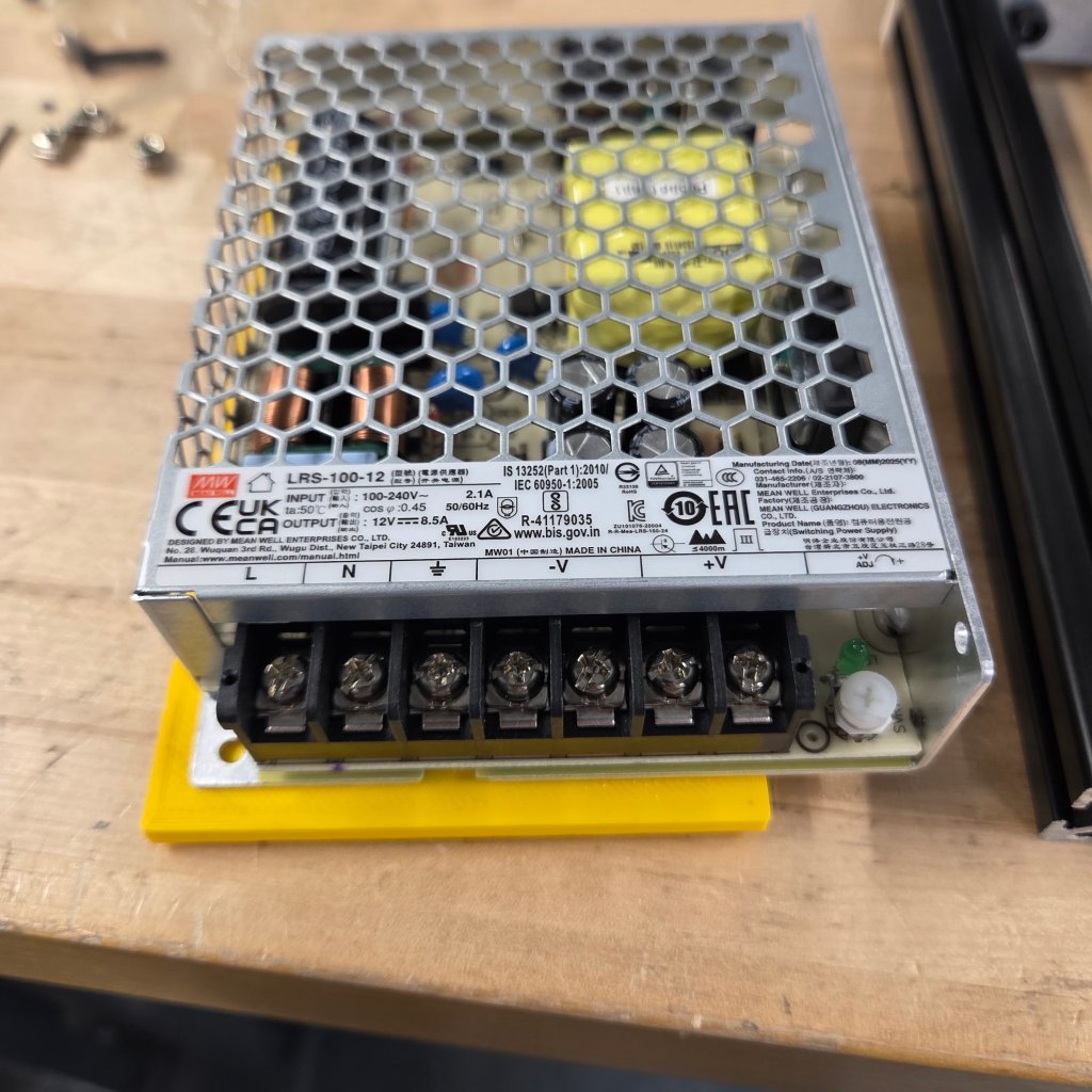
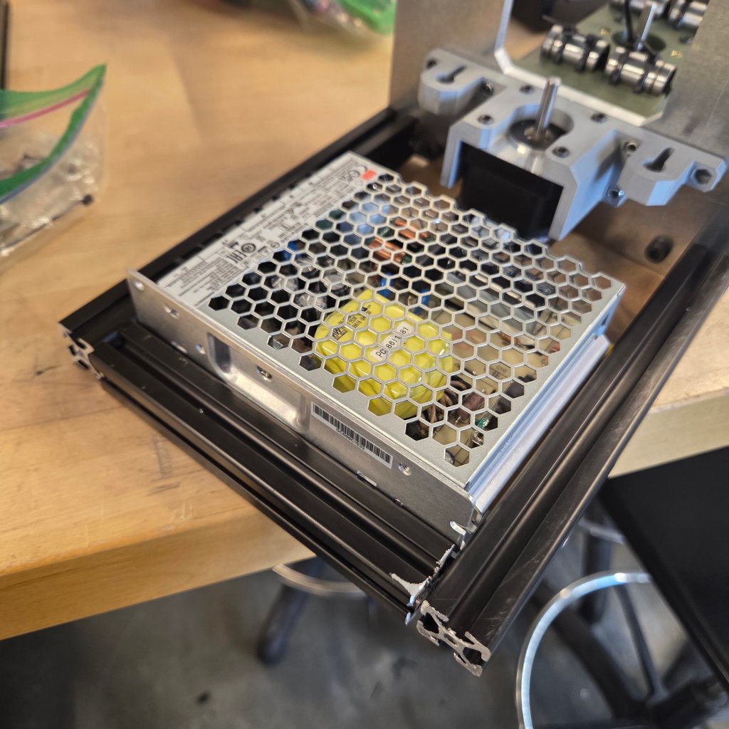
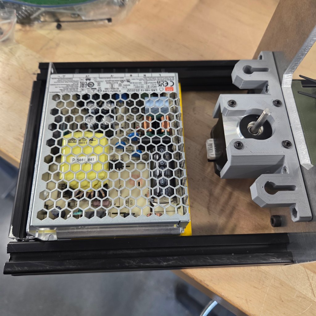
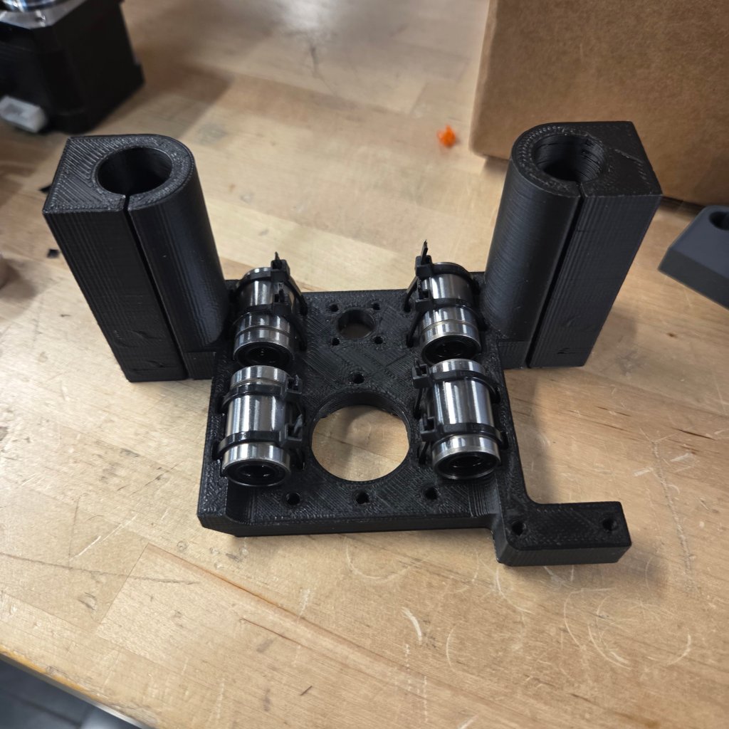
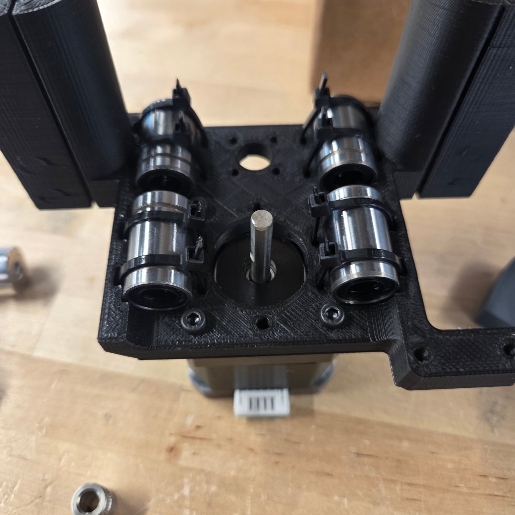
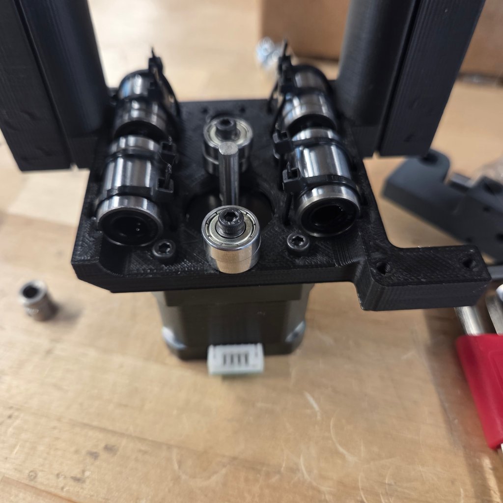
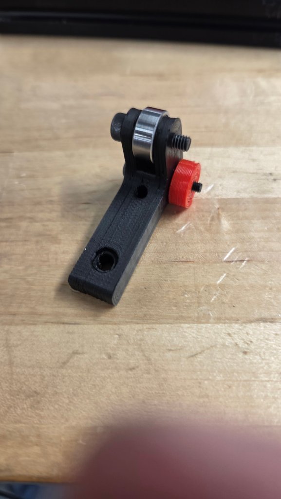
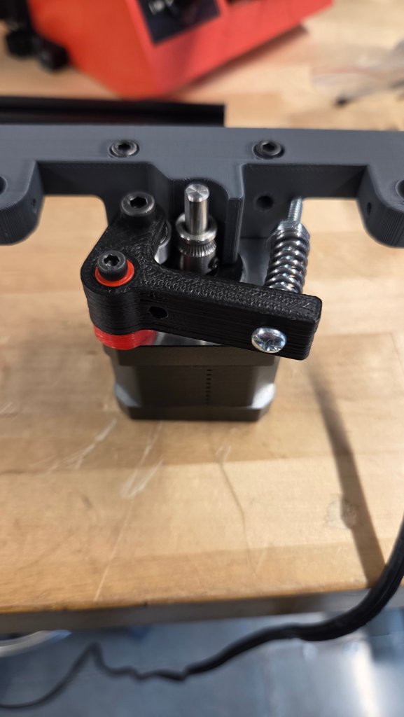
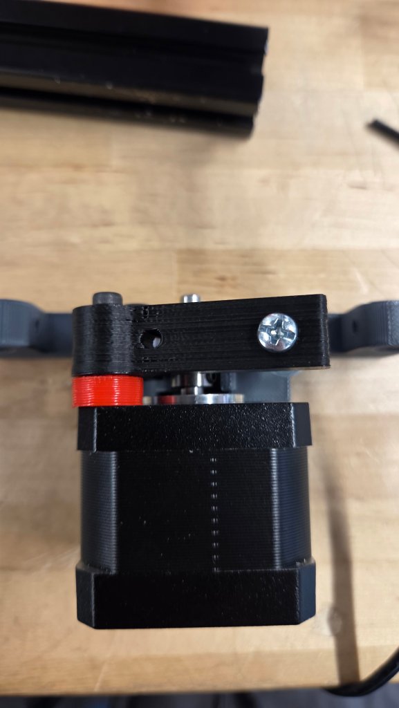
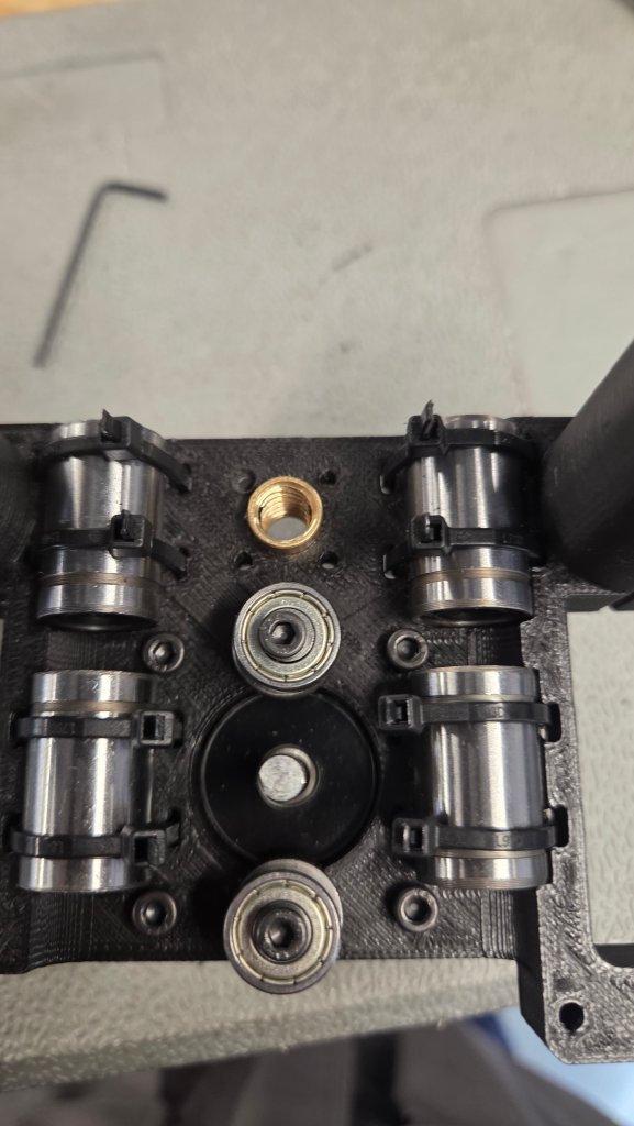
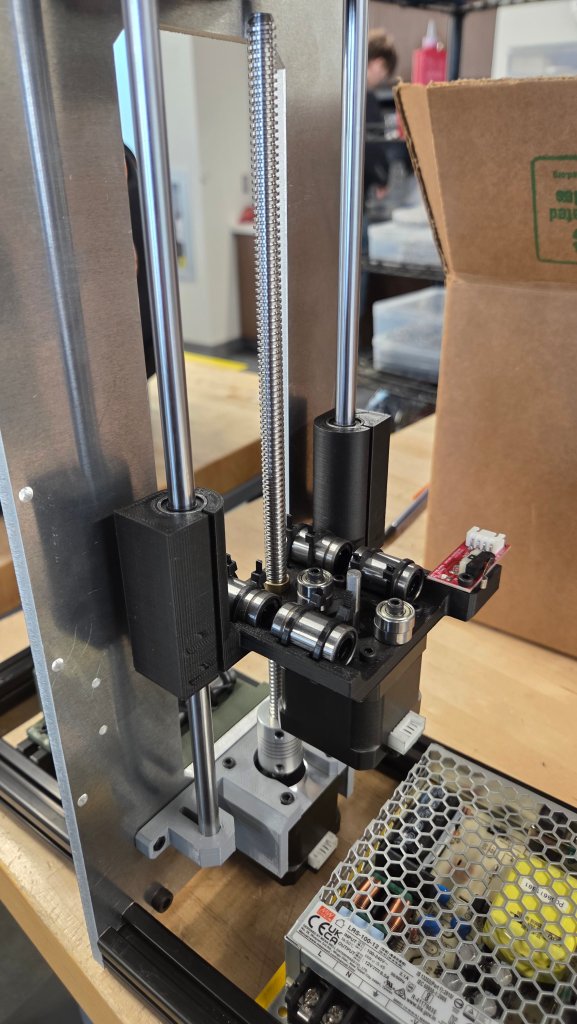
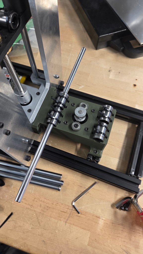
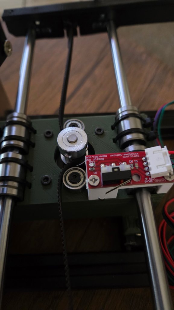
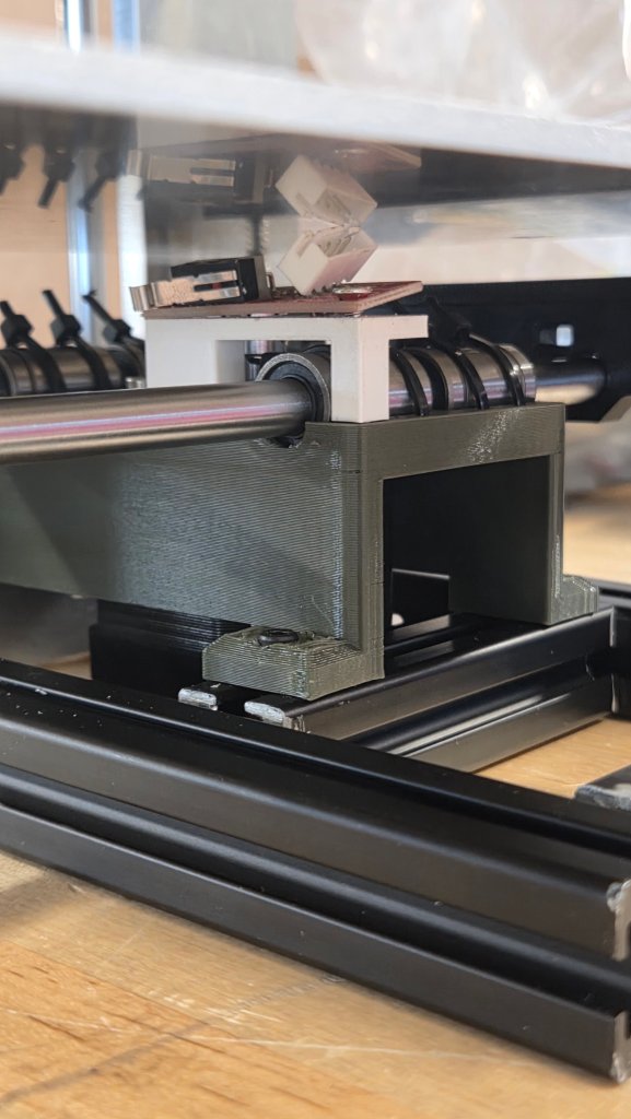
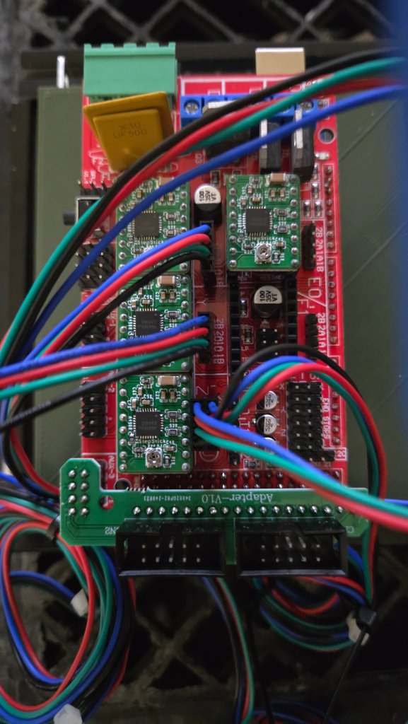
Zip-tie these long bearings in, you can snip the zip-ties down if you wantlplace the main electrical component onto this pieceuse washers on the bottomSlides on the other side, and you should slide everything so far into place.More zip-tieing to be down, this piece will be very necessary for the up and down action of the printer.MOTOR! it goes underneath this, I recommend flipping the outlet around from what is shown in the photo.Stack two bearings in these slots (The two helps with belt slipping in the future)Another motor, place this piece here, then bolt it down.This L shape piece, and the round T piece = put together and place a bearing in the place it fits, bolt it down as well.Attempt to place a spring, washer, and nut together and squeeze them into that hole in the photo, I would recommend screwing in the round T piece before putting the screw in the hole.
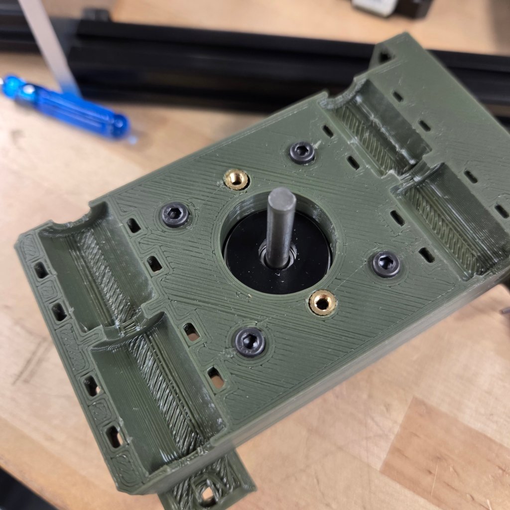
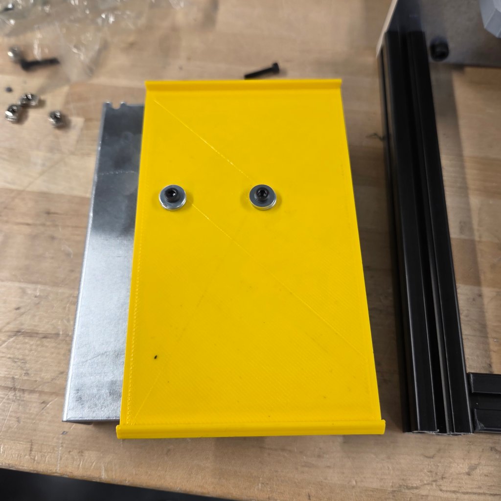
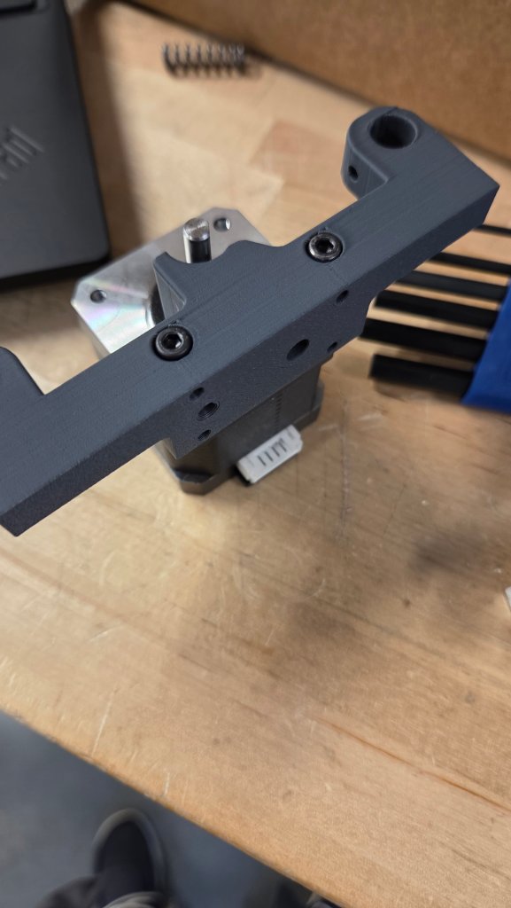
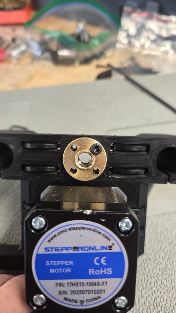
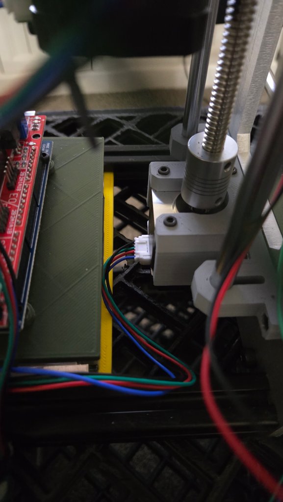
This gold-ish piece, heat it with a sauder and place it in this hole, then screw it in, I only screwed one hole in (it worked fine)
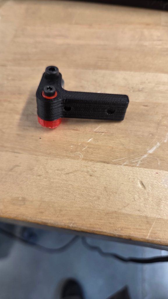
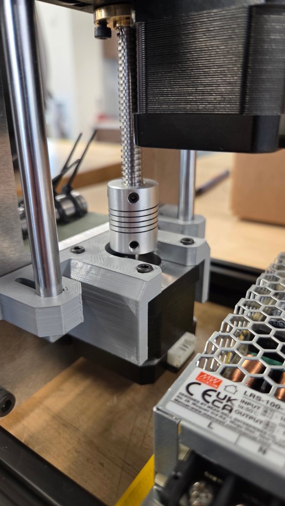
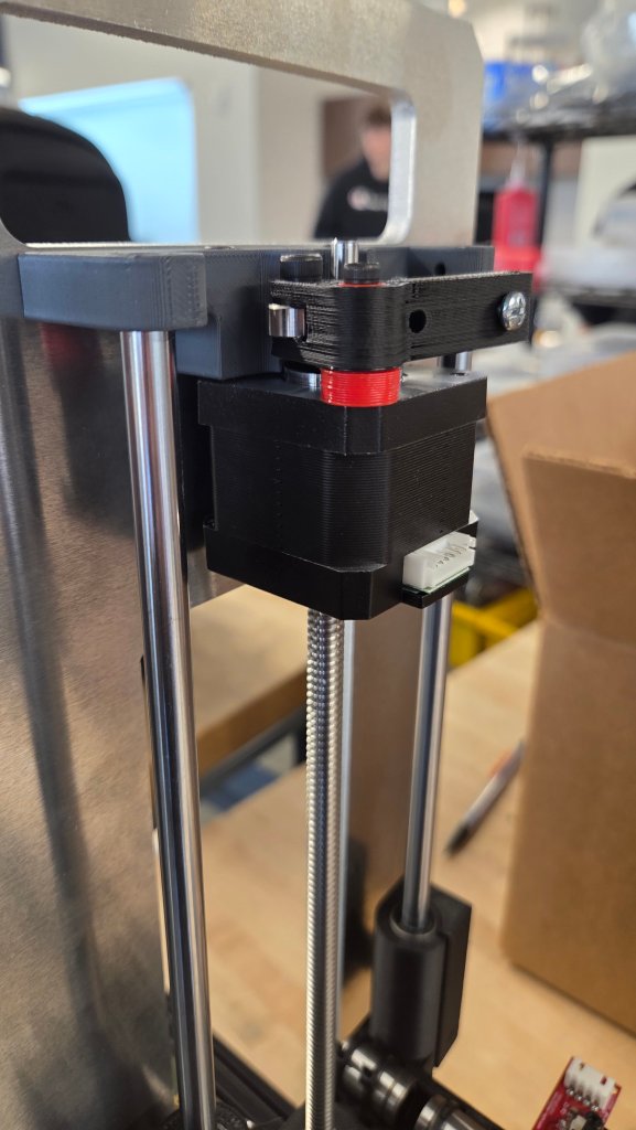
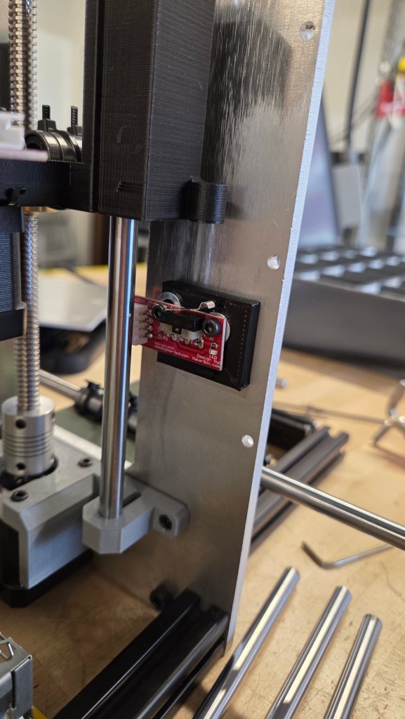
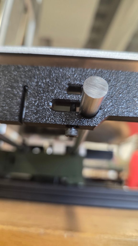
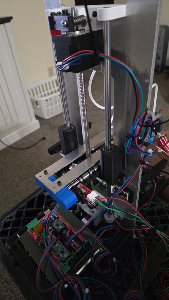
Screw the spiral rod into this piece, screw it to hold it in.Put these two rods into the two long bearing pieces.You will need to put a screw into this hole so you will be able to adjust your limit switch for the Z axis.Find rods that will be long enough or even TOO long for the base-plate.Place the belts and belt guider
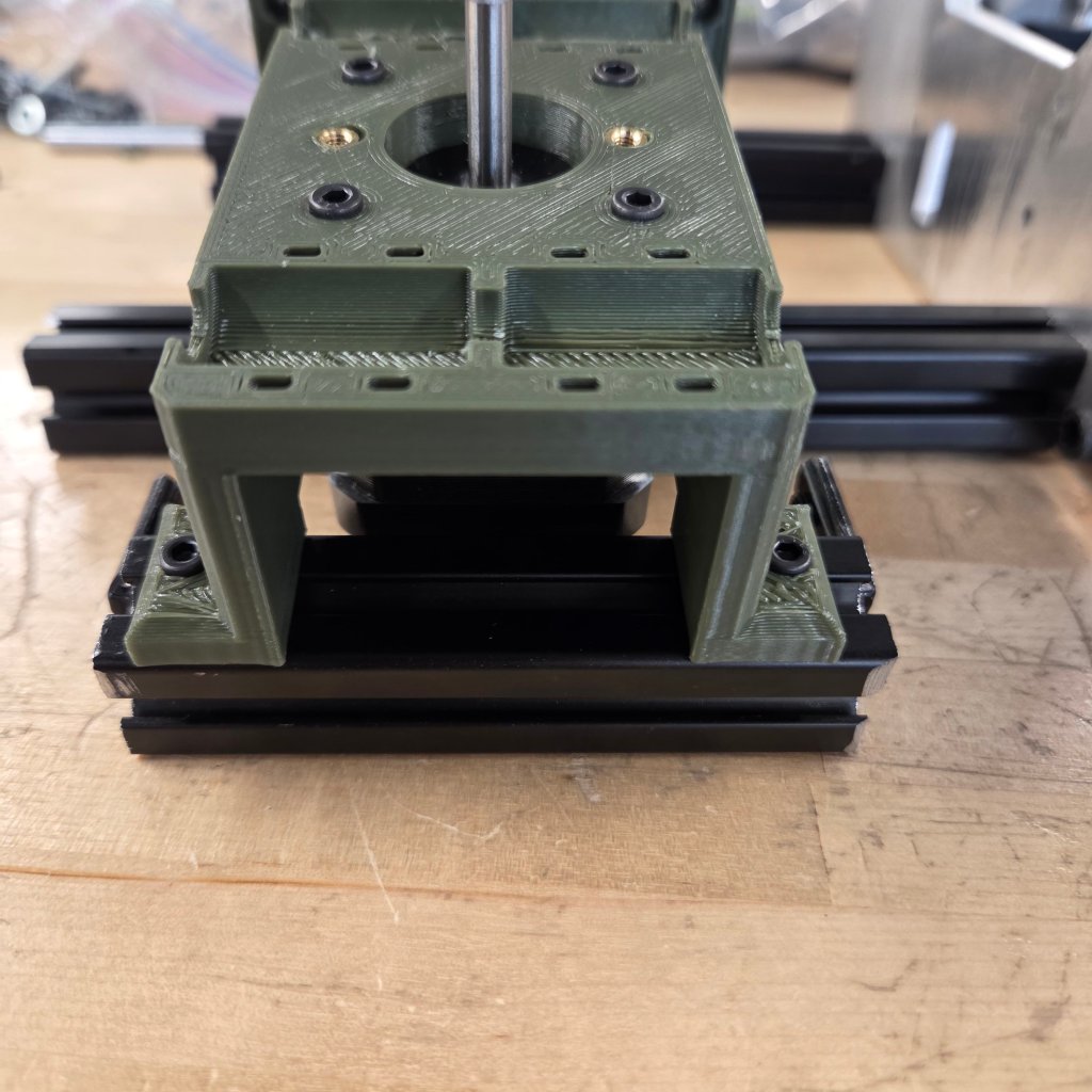
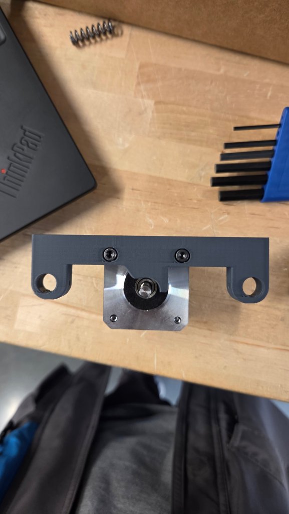
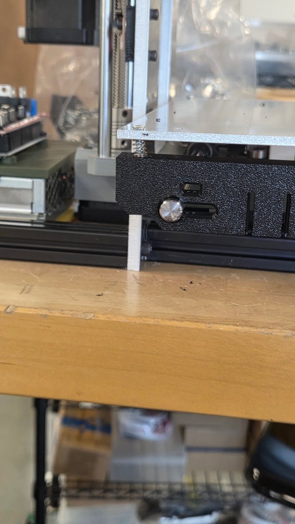
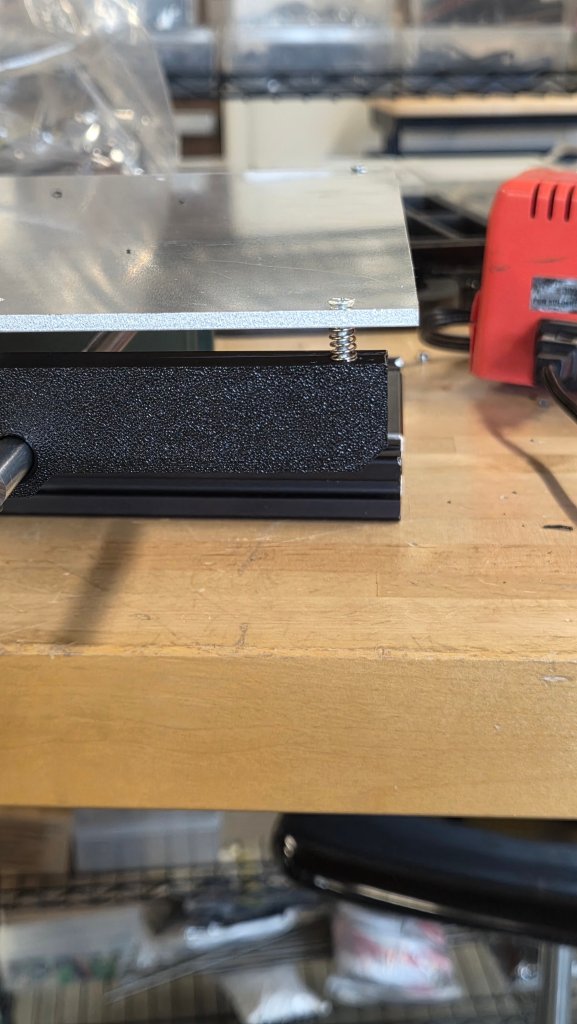
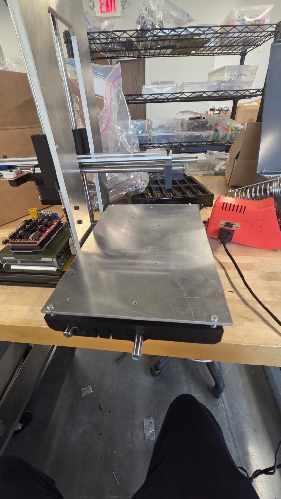
Grab these two 3D printed pieces, stick the rods where they go, place a nut in the slot, bolt it till it doesn’t move, then get springs and screws, screw the base plate down.
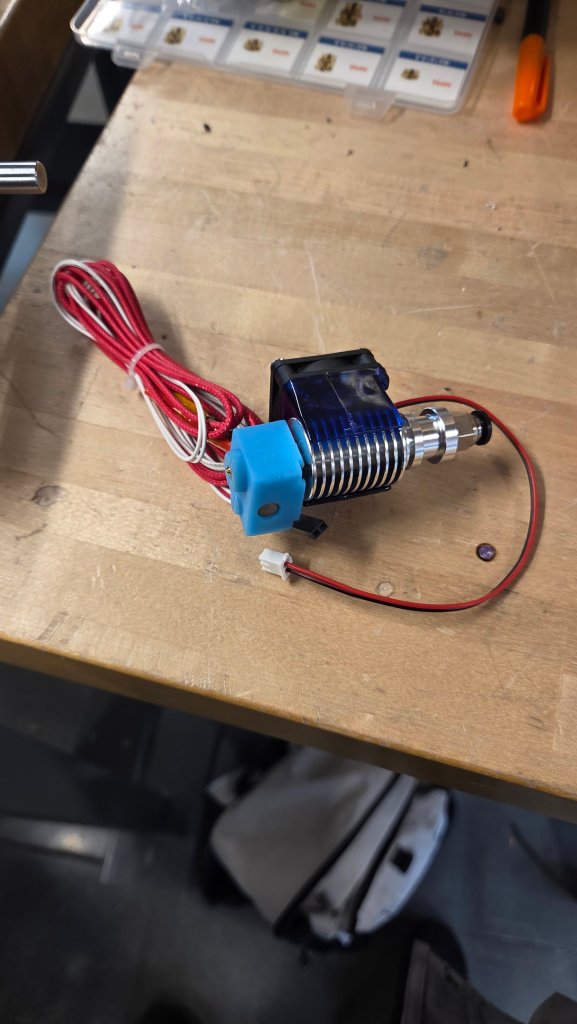
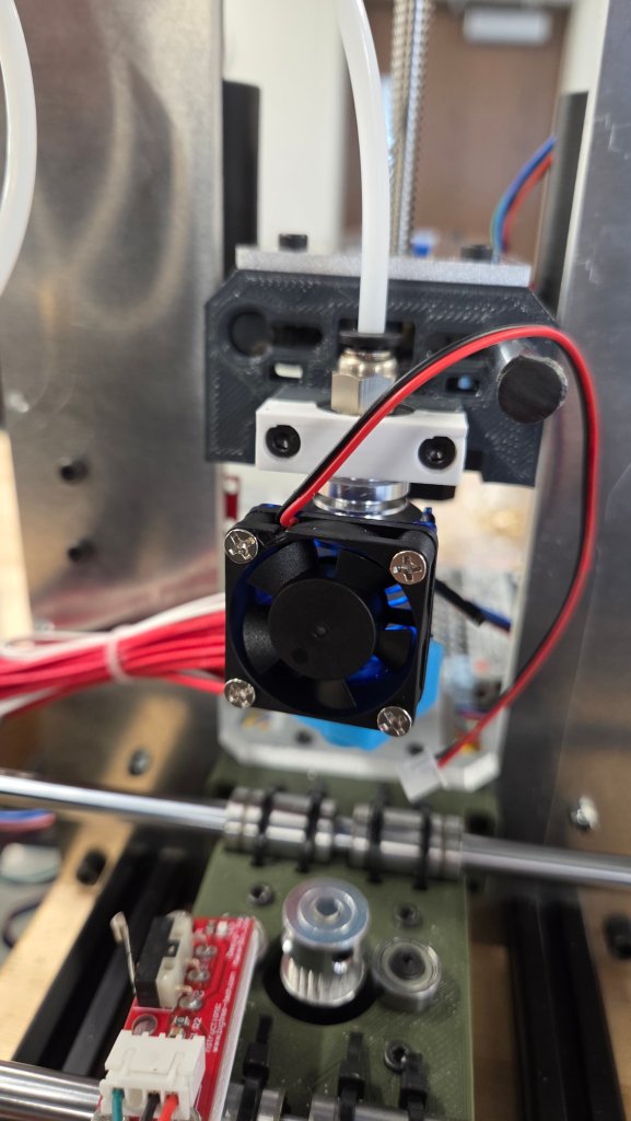
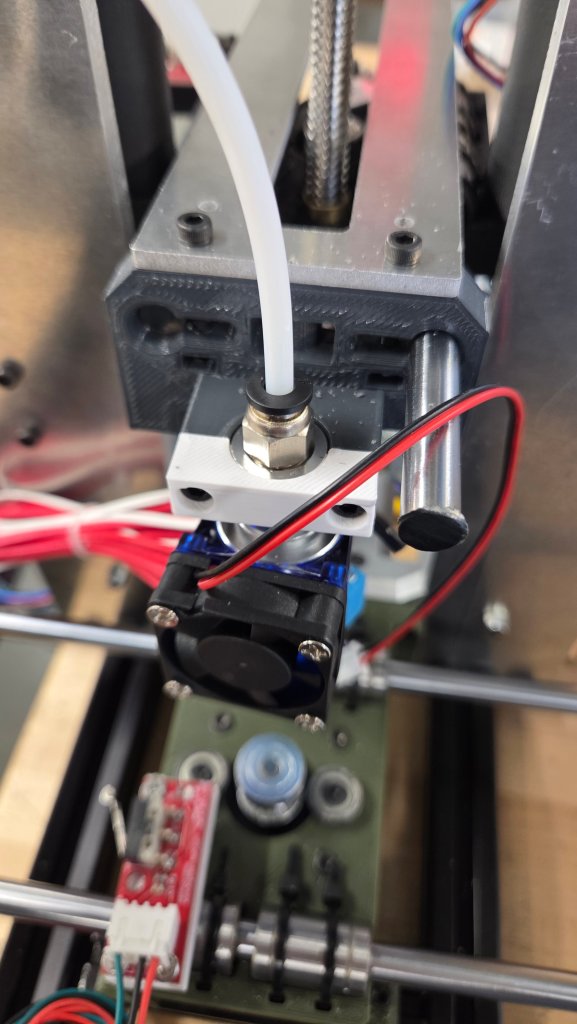
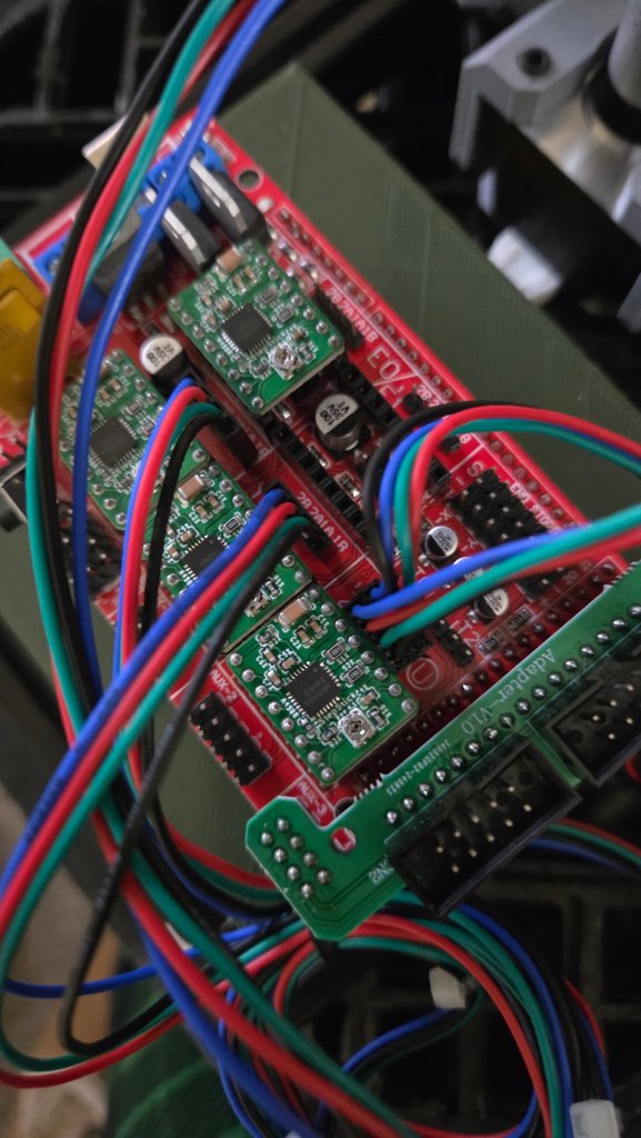
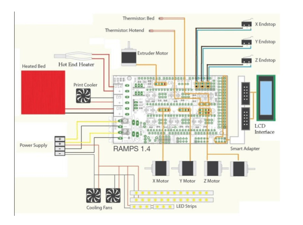
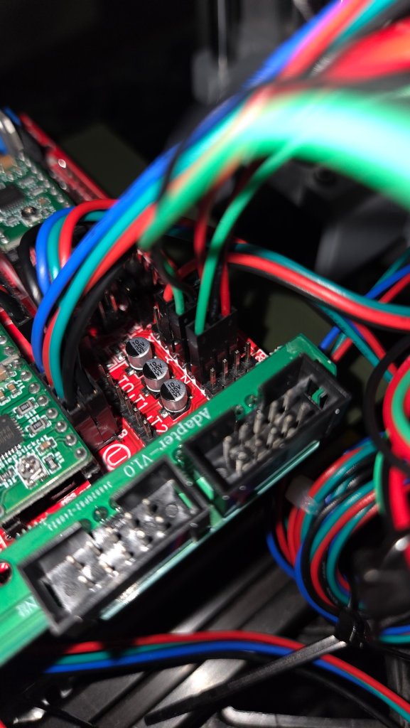
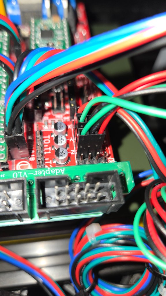
THE EXTRUDERPlace it on this part of the printer, you will need this piece.Plug all the wires into the motors.